IoT Project Retrospective
Part 2, Hardware
In the last retrospective, I talked about the overall IoT project and focused on the software side. This blog focuses on the hardware, specifically the local (in the home) hardware the forms the "Home Sensor Network" and comprises of :
- Hub
- Collection of sensor nodes
- Collection of switch nodes
- Hue and Energenie
Hub
Starting with the hub, this is the heart of the local network, it needs to form the mesh network (as the ZigBee controller node) and to act as a bridge with the back-end, by which it communicates over public internet.
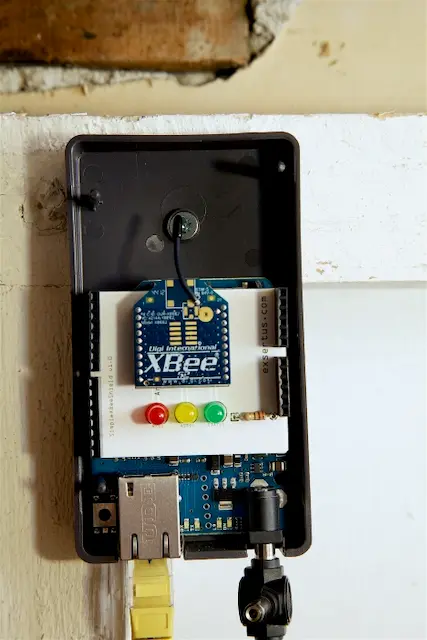 First generation hub, based around Arduino ethernet.
The latest iteration of the hub is based around a Raspberry Pi2 which is ample power for the task. The RPI is running Rasbian Stretch, which has been out for a few years or so and will no doubt be upgraded at some point. Since we are not using a UI, its running in headless mode with ssh (local) access.
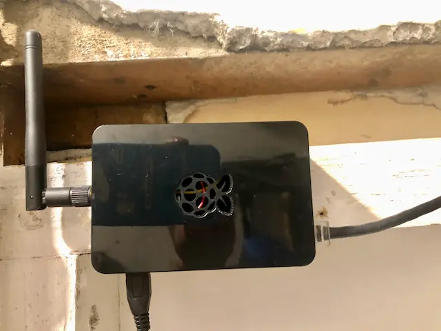 Current generation hub, based around RPI v2.
The core processing of the hub is managed by a Python3 script that runs as a background daemon / systemd. This nicely ensures the script starts on reboot etc.
The python script (xbeehub.py) itself is very much event driven, where it binds/listens to MQTT and the serial port of the attached XBee Pro Series 2 interface. Inbound MQTT requests (for the switch nodes) and inbound serial RX from the XBee hardware whenever a sensor sends a reading to the hub, or whenever a switch node responds to remote AT commands.
Binding the ZigBee library to the serial port
ser = serial.Serial(SERIAL_PORT,9600, timeout=TIMEOUT)
log.info("Serial: OK")

zb = ZigBee(ser, escaped=True, callback=handleXBeeEvent)
log.info("XBee: OK")
Now we bind and subscribe to the AWS MQTT library so that we can act on inbound MQTT requests from the back-end, specifically we can receive the switch requests from the back-end and sent the requests to turn on/off the switch nodes (sprinklers)
The AWS MQTT lib makes use of SSL certs for authentication and is managed via the standard AWS IoT "thing".
The abridged version where xbeeEventCallback, energenieEventCallback and hueEventCallback are the python functions that act on the env callback.
from AWSIoTPythonSDK.MQTTLib import AWSIoTMQTTClient

q = "%s/event/xbee" % CLIENT_NAME
myMQTTClient.subscribe(q, 1, xbeeEventCallback)
log.info("MQTT Subscribe to topic: %s" % q)

q = "%s/event/energenie" % CLIENT_NAME
myMQTTClient.subscribe(q, 1, energenieEventCallback)
log.info("MQTT Subscribe to topic: %s" % q)

q = "%s/event/hue" % CLIENT_NAME
myMQTTClient.subscribe(q, 1, hueEventCallback)
log.info("MQTT Subscribe to topic: %s" % q)
Sensor Nodes
Currently the nodes come in 2x flavours; sensor and switch. The sensor nodes as designed to be as low power as possible such that they can run for 2-3 years on a pair of AA batteries. Their primary function is to take sensor readings (temp, humidity - dependant on attached sensors) and to relay that to the hub, which subsequently logs it in the back-end.
Specifically, these nodes comprise of:
- ATTiny85 or ATTiny84 microprocessor that handles the control and flow
- XBee series 2(ZB) module as the radio operating in AT mode and using the endpoint firmware.
- Custom PCB board to house the components
- Attached sensors; moisture, temperature, pressure etc
Here's an example of the early prototype using a CR2032 battery which lead to the conclusion that running 2x AA is a much better way to go!
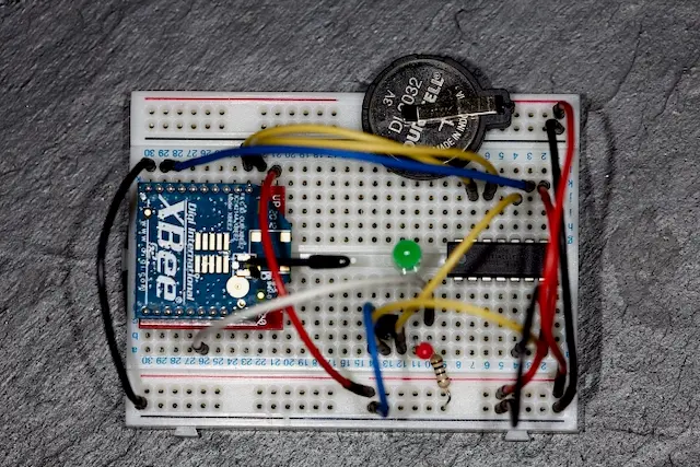 Prototyping the sensor nodes on a breadboard
Over time, the variants have been baked into the following custom PCB's that I've design. From left to right:
- ATTiny84 + I2C
- ATTiny85 + Temp+Moisture sensor
- ATTiny85 + Temp sensor
- ATTiny85 + Emon power sensor
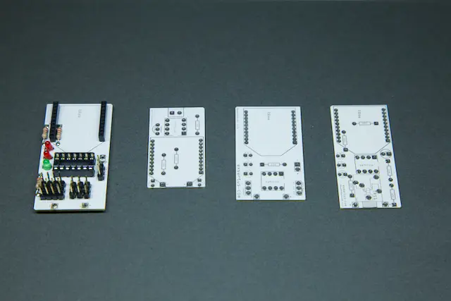 Custom PCB's
As indicated above, there are a number of flavours of sensor based around what they are sensing. However, the core principles remains for all:
- ATTiny uses watchdog to run in a sleep state, and periodically wakes to take sensor reading, transmits it, before returning back to sleep
- Comms between ATTiny and XBee are serial (TX only) and use the raw AT command protocol, rather than API (not enough memory on the CPU to do this). In essence, the TX payload is a string thats written to the serial out.
- All sensor nodes are based around 2x AA batteries.
The current flavours/variants of sensor are outlined below. Each variant has its own board design based around ATTiny84 vs. ATTiny85, and the sensor type. Typically the ATTiny84 is utilized when more input or output pins are required.
| Variant | Description | Micro Controller | Sensor(s) | Sample Rate |
|---|---|---|---|---|
| Current clamp | Measures current from 100A home supply, using non-invasive current clamp + Emon lib to calculate power. Board design (Fritzing): XBeeEmonSensor85_1.0.fzzCode: XBeeEMONSensor.ino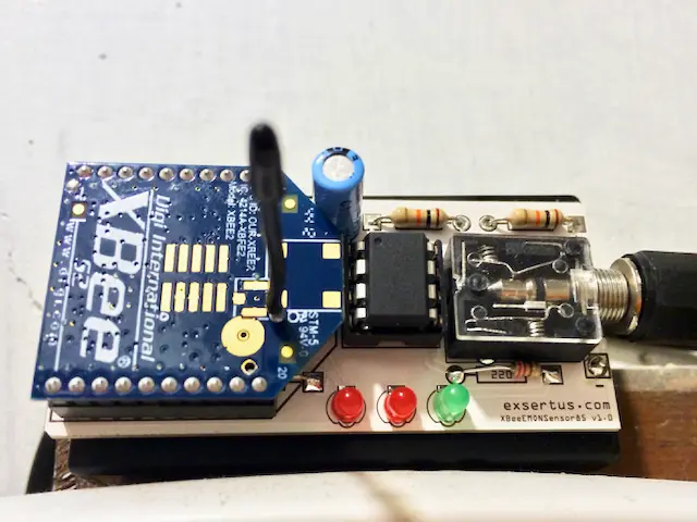 | ATTiny85 | Current clamp (100A). | 1 min, but upload every 10 mins |
| Temp & Moisture | Designed to put in plant pots to monitor and alert on soi moisture. The moisture probes are designed to be disposable (due to gradual corrision) - just 10cm lengths of 18 SWG piano wire. Board design (Fritzing): XBeeTempMoist-85-1_0.fzzCode: XBeeTempMoistureSensor2.ino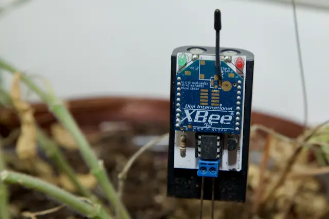 | ATTiny85 | Moisture probe & TMP36 | 15 mins |
| Temp & Pressure | General I2C experimental node with BMP085 sensor measuring temperature and barometric pressure. Board design (Fritzing): XBeeSensor84_1.1.fzzCode: XBeeBMP085Sensor2.ino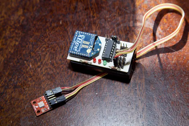 | ATTiny84 | BMP085 | 15 mins |
| Temp | First sensor node iteration, a simple temperature sensor for measuring ambient room temp. Board design (Fritzing): XBeeSensor85_1.2.fzzCode: XBeeTempSensor2.ino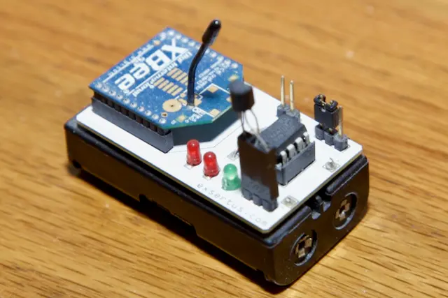 | ATTiny85 | TMP36 | 15 mins |
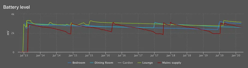
As you can see from the sample rate column, the CPU logic (which I'll describe in a minute), separates the "sample" and "upload" stages, meaning that multiple samples can be taken, then bulk uploaded. This was designed through testing, as it was found that the most expensive (power) step is enabling the XBee radio, and sending the data. This approach was developed for the mains sensor to enable a sample rate of 1 min whilst maximizing the battery life. See graph below on battery life durations.
All other nodes typically stick to a "sample" + "send" cycle of 15 mins, ie wake up, sample, send to hub, then back to sleep.
The graph below shows historical discharge times. Headlines:
- Mains sensor ~1 year
- Moisture sensor ~4 years
- Pressure & Temp sensor (BMP085) ~4 years
- Single temp sensor (TMP36) ~ 6 years
 Historical sensor node, battery discharge times
Switch Nodes
At present there is only a single variant of the switch node and only really one in operation. The switch nodes differ from the sensor nodes in that:
- Contains no sensors.
- Contains 2x TIP120G darlington transistors for 12v switching
- Designed to be powered all the time (typically by 12v)
- No micro-controller, instead using the output pins on the XBee itself connected to TIP120G darlington transistors.
- Since these nodes are powered, the XBee radios are configured as routers rather than endpoints, which helps boost the mesh network.
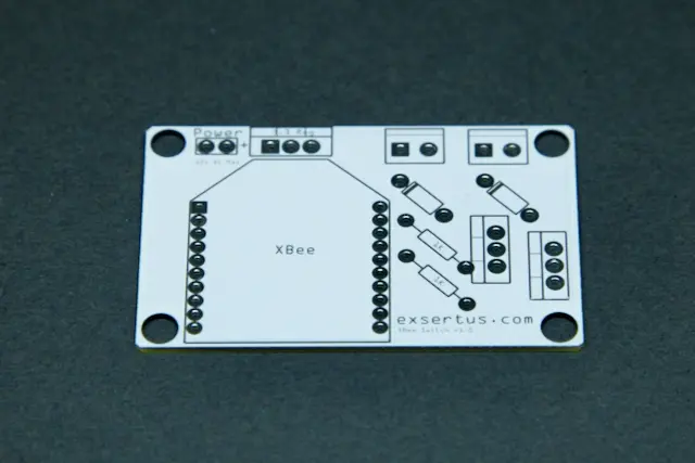 Switch board, unpopulated
In essence, the board is simply acting as a framework to allow the XBee output pins to switch a 12v DC load. In the current use case, I have a 12v solenoid water valve attached to each "channel", hence providing water flow control to 2x routes, which are feed from mains water supply.
I have been looking at a "water butt + 12v pump" variant, but can't seem to get the right water pressure. However, the electronics and approach is exactly the same, just switching a 12v pump, rather than a solenoid valve.
Hue & Energenie
Whilst these aren't physical nodes, the local hub is communicating to both Hue and Energenie controllers on my local home network (IP based). At this stage, its more of an experiment.
More posts in this series:
- Part 1, Software
- Part 2, Hardware