Modular Synthesizer Project
Part 4 - VCF
Finally onto the filter!, squelchy-ness abounds!
This module design is another inspired and relatively simple filter from LookMumNoComputer and its based around how the Korg35 chip works.
The circuit is based around the LM13700 operational transconductance amplifier (yeah, I had to Google that too). We'll use the same IC on the VCA module too. Its another old classic IC for voltage control, and offers 2x independent channels which in this module well use to control the cut-off frequency and the resonance. More about what that means in a bit!
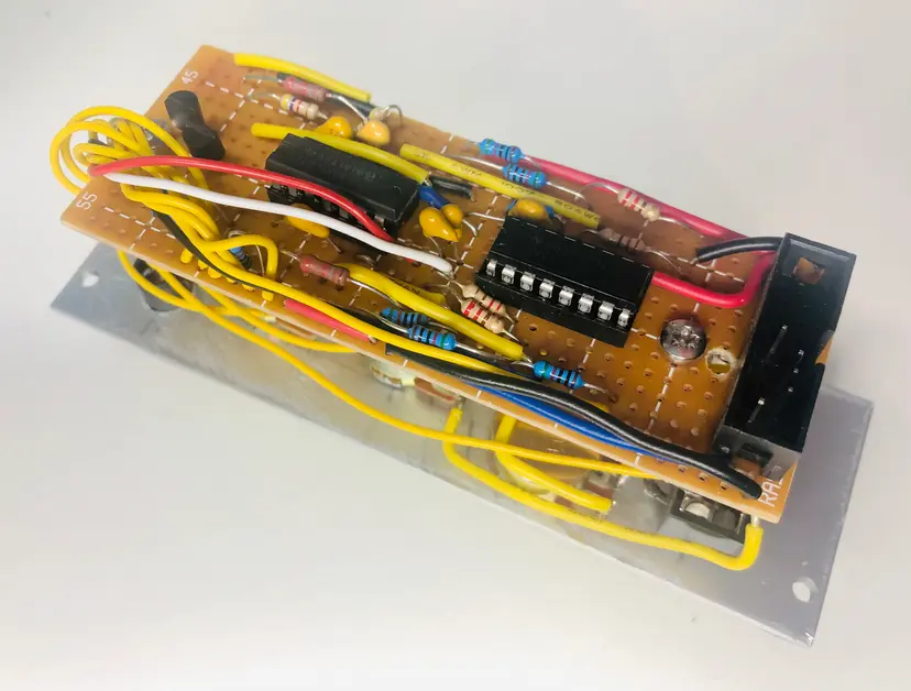 Rear
RearStepping back to basics, there is a great article on filters here
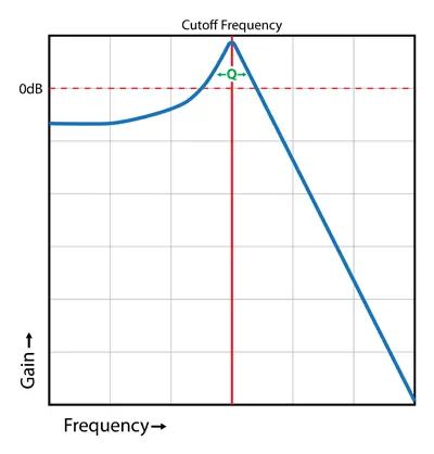 Filter curve from (https://synthesizeracademy.com)
Filters come in many types, but at the most simplest level there are 3:
- Low pass: Allows low frequencies to pass through, and stops high frequencies
- High Pass: The inverse of a low pass; ie allows high frequencies, but stops low frequencies
- Band pass / stop: These operate between a range (low and high) and in the case of band pass; only allow frequencies through that are in that range. In the case of band stop or notch filters, these allow only frequencies outside of the range to pass.
In my case, I went for a LPF, which is the most common filter for analog synths and its the one that gives that lovely growl as you open up the cut-off and whack the resonance up.
There are 2x basic controls for a LPF:
- Cut-off frequency - Controls the frequency at which the filter starts to filter out higher frequencies, thus making the sound less bright and more dull.
- Resonance - Controls the Q factor or resonance amount at which the signal is boosted (attenuated) at the cut-off frequency. This attenuation is essentially controlled feedback that creates harmonics in the waveform.
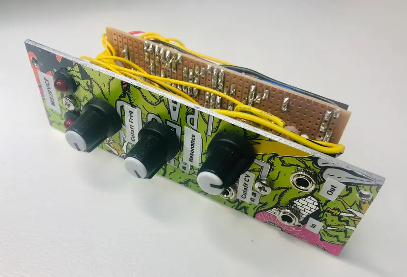 Front panel
Whilst is nice to tweak the knobs manually, its far better to modulate these with voltage control. This circuit uses CV input (0-10v) to control the cut-off value. In real terms it means the openness/closeness of the filter can be controlled over time, given that sweeping or fading affect. Typically a VCF's CV input is triggered from an envelope generator like the one we covered in the last blog.